L&TD
LOGGING & TESTING DIVISION
MWD/LWD
I/ INTRODUCTION
Measuring the properties of geological formations and reservoir fluids has traditionally been performed with logging tools run on an electric wireline, a technique that was developed in the 1920’s.
For a long time this was the only method of acquiring accurate subsurface data in boreholes. The benefits of wireline logging are obvious - the measurements are performed in a static environment, the contact between the tools and the formation is good, the depth control is excellent, and the tools used are proven through several decades of operations. With high rig costs and increased focus on operational efficiency, there are also certain inherent disadvantages with wireline logging. The data acquisition requires a halt in the drilling operation and, given that there is a problem in getting the tool into the hole or retrieving it, wireline logging introduces added risk for time delays and in a worst-case scenario, the hole may be lost. Wireline logging is therefore now used in wells with added focus on the quality of the formation data, in wells where the risk of getting stuck is low, or where there is a requirement for specialized services, such as sampling of formation fluids.
STEERING THE DRILL-BIT
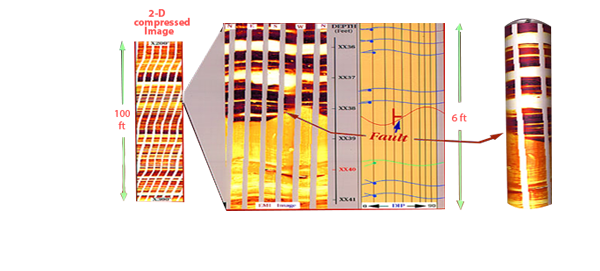
Since the early 1980’s, huge resources have been spent on developing a method to perform data acquisition simultaneously with the drilling operations, i.e. in real time. This technique is called Logging While Drilling (LWD). Since the introduction of the Gamma Ray tool more than 20 years ago, there has been a rapid development of more advanced LWD measurements. Through LWD, it is possible to optimize well positions, avoid drilling hazards and drill more efficiently. The operators expect the downhole data to be as updated as possible, i.e. they want real-time data and data acquired as close to the drill bit as feasible. Recent developments in LWD have made it possible to acquire high-resolution electrical borehole images. For the geologist, real-time interpretation of structural and sedimentary features from borehole images can be used to steer the drill bit in the reservoir section. The purpose would be to stay inside a desired sedimentary package based on the rapid interpretation of sedimentological criteria (e.g. sedimentary
steering by using predictive models of sandbody geometry and internal architecture). This can give forewarning of approaching features in the proposed drill path, such as.fracture intensity increasing towards a fault zone, and avoid or mitigate adverse features that may have a negative impact production , for example by avoiding reservoir roof rocks by steering away in advance.
II/ MWD AND LWD
Measurement While Drilling (MWD)
MWD includes measurement and acquisition of directional data (wellbore inclination and azimuth), pressure in the wellbore and drilling dynamics measurements such as vibration and shock. MWD thus provides geometrical information on well position and helps to drill the well safely and efficiently.
Logging While Drilling (LWD)
LWD is logging the properties of the formation and reservoir fluids while drilling and before drilling fluids invade the formation, similar to open-hole, wireline logs.
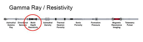
The most frequently used measurements include gamma ray, resistivity, density, porosity, acoustic travel time and formation pore pressure.
THE TECHNOLOGY
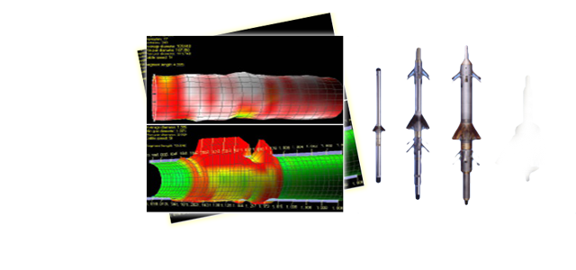
Logging While Drilling (LWD) is a technique of conveying well logging tools into the well borehole downhole as part of the bottom hole assembly (BHA).
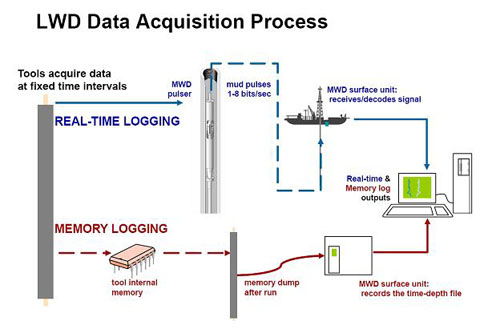
LWD tools work with its Measurement While Drilling (MWD) system to transmit partial or complete measurement results to the surface via typically a drilling mud pulser or other improved techniques, while LWD tools are still in the borehole, which is called "Real Time Data". Complete measurement results can be downloaded from LWD tools after they are pulled out of hole, which is called "Memory Data".
LWD technology was developed originally as an enhancement to the earlier MWD technology to completely or partially replace wireline logging operation. With the improvement of the technology in the past decades, LWD is now widely used for drilling (including geosteering), formation evaluation (especially for real time and high angle wells).
Available LWD Measurements
LWD technology was originally developed to partial or complete replace wireline logging. Over the years, majority of the measurements have been made available in LWD. Certain new measurements are also development in LWD only. The following is an incomplete list of available measurement in LWD technology.
- Natural Gamma Ray (GR)
- Total Gamma Ray
- Spectral Gamma Ray
- Azimuthal Gamma Ray
- Gamma ray close to drill bit.
- Density and Photoelectric Index
- Neutron Porosity
- Borehole Caliper
- Ultra sonic azimuthal caliper.
- Density Caliper
- Resistivity (ohm-m)
- Attenuation and phase shift resistivities at different transmitter spacings and frequencies.
- Resistivity at the drill bit.
- Deep directional resistivities
- Sonic
- Compressional Slowness(Δtc)
- Shear Slowness (Δts)
- Borehole Images
- Density Borehole Image
- Resistivity Borehole Image
- Formation Tester and Sampler
- Formation Pressure
- Formation Fluid Sample
- Nuclear Magnetic Resonance (NMR)
- Seismic While Drilling (SWD)
- Drillbit-SWD
- VSP-WD (Vertical Seismic Profile While Drilling)
MWD stands for Measurement While Drilling in the Oil Industry. Is a system developed to perform drilling related measurements downhole and transmit information to the surface while drilling a well. MWD tools are conveyed downhole as part of bottom hole assembly (BHA). The tools are either contained inside a drill collar (sonde type) or are built into the collars themselves.
MWD systems can take several measurements like natural gamma ray, directional survey, tool face, borehole pressure, temperature, vibration, shock, torque etc. Some advanced MWD tools can even measure formation pressure and take formation samples. The MWD also provides the telemetry for operating rotary steering tools (RSTs).
The measured results are stored in MWD tools and some of the results can be transmitted digitally to surface using mud pulser telemetry through the mud or other advanced technology.
Certain MWD systems have the capability of receiving encoded control commands which are sent by turning on and off mud pumps and/or changing the rotation speed of drill pipe or by other advanced telemetry technology such as wired pipe.
Types of information transmitted
Directional information
MWD tools are generally capable of taking directional surveys in real time. The tool uses accelerometers and magnetometers to measure the inclination and azimuth of the wellbore at that location, and they then transmit that information to the surface. With a series of surveys at appropriate intervals (anywhere from every 30 ft (ie 10m) to every 500 ft), the location of the wellbore can be calculated.
MWD tools are extremely complex pieces of high- tech electronics.
By itself, this information allows operators to prove that their well does not cross into areas that they are not authorized to drill. However, due to the cost of MWD systems, they are not generally used on wells intended to be vertical. Instead, the wells are surveyed after drilling through the use of Multishot Surveying Tools lowered into the drillstring on slickline or wireline.
The primary use of real-time surveys is in Directional Drilling. For the Directional Driller to steer the well towards a target zone, he must know where the well is going, and what the effects of his steering efforts are.
MWD tools also generally provide toolface measurements to aid in directional drilling using downhole mud motors with bent subs or bent housings. For more information on the use of toolface measurements, see Directional Drilling.
Drilling mechanics information
MWD tools can also provide information about the conditions at the drill bit. This may include:
- Rotational speed of the drillstring
- Smoothness of that rotation
- Type and severity of any vibration downhole
- Downhole temperature
- Torque and Weight on Bit, measured near the drill bit
- Mud flow volume
Use of this information can allow the operator to drill the well more efficiently, and to ensure that the MWD tool and any other downhole tools, such as Mud Motors, Rotary Steerable Systems, and LWD tools, are operated within their technical specifications to prevent tool failure. This information also is valuable to Geologists responsible for the well information about the formation which is being drilled.
Formation properties
Many MWD tools, either on their own, or in conjunction with separate Logging While Drilling tools, can take measurements of formation properties. At the surface, these measurements are assembled into a log, similar to one obtained by wireline logging.
LWD Logging While Drilling tools are able to measure a suite of geological characteristics including- density, porosity, resistivity, acoustic-caliper, inclination at the drill bit (NBI), magnetic resonance and formation pressure.
The MWD tool allows these measurements to be taken and evaluated while the well is being drilled. This makes it possible to perform Geosteering, or Directional Drilling based on measured formation properties, rather than simply drilling into a preset target.
Most MWD tools contain an internal Gamma Ray sensor to measure natural Gamma Ray values. This is because these sensors are compact, inexpensive, reliable, and can take measurements through unmodified drill collars. Other measurements often require separate Logging While Drilling tools, which communicate with the MWD tools downhole through internal wires.
Measurement while drilling can be cost-effective in exploration wells, particularly in areas of the Gulf of Mexico where wells are drilled in areas of salt diapirs. The resistivity log will detect penetration into salt, and early detection prevents salt damage to bentonite drilling mud.
Data transmission methods
Mud pulse telemetry
Mud pulse telemetry is today the most commonly used method of transmitting data from the measurement tools in the well-bore to the rig at the surface. While drilling, mud is pumped from the surface down through the drill-string, through the measurement and logging tools (MWD/LWD), then through the drill bit and back to the surface through the annulus between the drill-string and formation. The increase in number of advanced measurements puts a higher demand on data transmission speed. Mud pulse telemetry is limited with regard to bandwidth and can only give 10-12 bits per second (bps) data transmission. To maximise the real-time value from the advanced measurements, will need kilo-bps capacity. The newly introduced wired drillpipe technology can be the solution for supplying this capacity. Several oil companies in the North Sea are currently planning test runs.
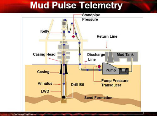
Downhole a valve is operated to restrict the flow of the drilling mud (slurry) according to the digital information to be transmitted. This creates pressure fluctuations representing the information. The pressure fluctuations propagate within the drilling fluid towards the surface where they are received from pressure sensors. On the surface, the received pressure signals are processed by computers to reconstruct the information. The technology is available in three varieties - positive pulse, negative pulse, and continuous wave.
Positive Pulse
Positive Pulse tools briefly close and open the valve to restrict the mud flow within the drill pipe. This produces an increase in pressure that can be seen at surface. Line codes are used to represent the digital information in form of pulses.
Negative Pulse
Negative pulse tools briefly open and close the valve to release mud from inside the drillpipe out to the annulus. This produces a decrease in pressure that can be seen at surface. Line codes are used to represent the digital information in form of pulses.
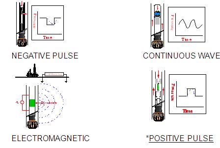
Continuous Wave
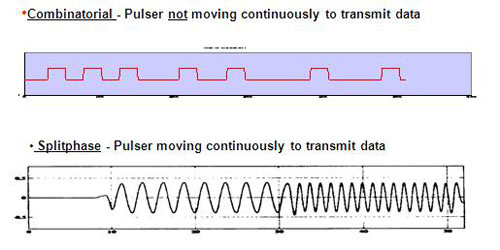
Continuous wave tools gradually close and open the valve to generate sinusoidal pressure fluctuations within the drilling fluid. Any digital modulation scheme with a continuous phase can be used to impose the information on a carrier signal. The most widely used modulation scheme is continuous phase modulation.
Signal Decoding
When underbalanced drilling is used, mud pulse telemetry can become unusable. This is because usually in order to reduce the equivalent density of the drilling mud a compressible gas is injected into the mud. This causes high signal attenuation which drastically reduces the ability of the mud to transmit pulsed data. In this case it is necessary to use methods different from mud pulse telemetry, such as electromagnetic waves propagating through the formation or wired drill pipe telemetry.
Current mud pulse telemetry technology offers a bandwidths of up to 40 bps. The data rate drops with increasing length of the wellbore and is typically as low as 1.5 bps - 3.0 bps. (bits per second) at a depth of 35,000 ft - 40,000 ft (10668 m - 12192 m).
Surface to down hole communication is typically done via changes to drilling parameters, i.e. change of the rotation speed of the drill string or change of the mud flow rate. Making changes to the drilling parameters in order to send information can require interruption of the drilling process, which is unfavorable due to the fact that it causes non-productive time.
Electromagnetic telemetry (EM Tool)
These tools incorporate an electrical insulator in the drillstring. To transmit data the tool generates an altered voltage difference between the top part (the main drillstring, above the insulator), and the bottom part (the drill bit, and other tools located below the insulator of the MWD tool). On surface a wire is attached to the wellhead, which makes contact with the drillpipe at the surface. A second wire is attached to a rod driven into the ground some distance away. The wellhead and the ground rod form the two electrodes of a dipole antenna. The voltage difference between the two electrodes is the receive signal that is decoded by a computer.
The EM tool generates voltage differences between the drillstring sections in the pattern of very low frequency (2-12Hz) waves. The data is imposed on the waves through digital modulation.
This system generally offers data rates of up to 10 bits per second. In addition, many of these tools are also capable of receiving data from the surface in the same way, while mud pulse-based tools rely on changes in the drilling parameters, such as rotation speed of the drillstring or the mud flow rate, to send information from the surface to downhole tools. Making changes to the drilling parameters in order to send information to the tools generally interrupts the drilling process, causing lost time.
Compared to mud pulse telemetry, electronic pulse telemetry is more effective in certain specialized situations, such as underbalanced drilling or when using air as drilling fluid. However, it generally falls short when drilling exceptionally deep wells, and the signal can lose strength rapidly in certain types of formations, becoming undetectable at only a few thousand feet of depth.
Wired Drill Pipe
Several oilfield service companies are currently developing wired drill pipe systems. These systems use electrical wires built into every component of the drillstring, which carry electrical signals directly to the surface. These systems promise data transmission rates orders of magnitude greater than anything possible with mud pulse or electromagnetic telemetry, both from the downhole tool to the surface, and from the surface to the downhole tool. The IntelliServ wired pipe network, offering data rates upwards of 1 megabit per second, became commercial in 2006. Representatives from BP America, StatoilHydro, Baker Hughes INTEQ, and Schlumberger presented three success stories using this system, both onshore and offshore, at the March, 2008 SPE/IADC Drilling Conference in Orlando, Florida.
Retrievable tools
MWD tools may be semi-permanently mounted in a drill collar (only removable at servicing facilities), or they may be self-contained and wireline retrievable.
Retrievable tools, sometimes known as Slim Tools, can be retrieved and replaced using wireline through the drill string. This generally allows the tool to be replaced much faster in case of failure, and it allows the tool to be recovered if the drillstring becomes stuck. Retrievable tools must be much smaller, usually about 2 inches or less in diameter, though their length may be 20 feet or more. The small size is necessary for the tool to fit through the drillstring, however, it also limits the tool's capabilities. For example, slim tools are not capable of sending data at the same rates as collar mounted tools, and they are also more limited in their ability to communicate with and supply electrical power to other LWD tools.
Collar-mounted tools, also known as Fat Tools, cannot generally be removed from their drill collar at the wellsite. If the tool fails, the entire drillstring must be pulled out of the hole to replace it. However, without the need to fit through the drillstring, the tool can be larger and more capable.
The ability to retrieve the tool via wireline is often useful. For example, if the drillstring becomes stuck in the hole, then retrieving the tool via wireline will save a substantial amount of money compared to leaving it in the hole with the stuck portion of the drillstring. However, there are some limitations on the process.
Limitations
Retrieving a tool using wireline is not necessarily faster than pulling the tool out of the hole. For example, if the tool fails at 1,500 ft (460 m) while drilling with a triple rig (able to trip 3 joints of pipe, or about 90 ft (30 m) feet, at a time), then it would generally be faster to pull the tool out of the hole than it would be to rig up wireline and retrieve the tool, especially if the wireline unit must be transported to the rig.
Wireline retrievals also introduce additional risk. If the tool becomes detached from the wireline, then it will fall back down the drillstring. This will generally cause severe damage to the tool and the drillstring components in which it seats, and will require the drillstring to be pulled out of the hole to replace the failed components, thus resulting in a greater total cost than pulling out of the hole in the first place. The wireline gear might also fail to latch onto the tool, or in the case of a severe failure, might bring only a portion of the tool to the surface. This would require the drillstring to be pulled out of the hole to replace the failed components, thus making the wireline operation a waste of time.
III/ THE BENEFITS OF MWD/LWD TECHNOLOGY
The LWD technology adds significant value for several reasons:
(a) Reservoir geometry is better understood by combining different log measurements with seismic data. The near-wellbore measurements, such as gamma ray and density wellbore images, can be used to interpret stratigraphy while the variety of resistivity measurements may be employed to interpret wellbore geometry. By combining this information with formation pressure and the seismic interpretation, the reservoir model may be improved. The understanding of log responses in horizontal wells is a key factor in this.
(b) Acoustic compressional (P) and shear wave data (S) are provided in a full range of formation types. In acoustic terminology, formations are split into fast and slow. Acquisition of shear waves in slow formations has been a challenge. The unique quadruple acoustic excitation method also enables the acquisition of quality shear data in the full range of formations (fast and slow).
(c) In minimal time, accurate formation pressure tests are acquired through a combination of good drilling practices, teamwork on the rig and the downhole intelligent optimisation system. Less than five minutes were needed to obtain three formation pressures per depth station. For these two case wells, formation pressures were acquired at a total of 62 depth stations, with a sealing efficiency of 98.5%. Formation pressure data was used for gradient plots and provided information on the type of reservoir fluid encountered and pressure communication in the reservoir.
In horizontal wells, special resistivity responses are experienced when crossing formation boundaries. Software processing methods such as inversion, enhance the measured resistivity. Combining inverted resistivity data with borehole image interpretation will help to enhance the determination of bed thickness as well as increase the accuracy of the true resistivity for that particular bed and improve the definition of the bed thickness. The result is a better definition of reservoir thickness and extent and a clearer idea of the amount of hydrocarbons present.
IN REAL-TIME
The family of LWD-services has developed into reliable and value-adding services for today’s advanced world of drilling and logging wells. The wealth of information now available in real-time helps to position the well accurately and facilitates in the mitigation of drilling hazards. The main advantages of using MWD and LWD are thus optimisation of well placement, increased operational efficiency by reducing non-productive-time, improved knowledge of the reservoir and hence, enhanced production.
The LWD technology is capable of operating with high reliability and at the same time delivering excellent data quality1
By collecting the data during drilling in a single run, the whole logging process is made more efficient and the wells are put on stream earlier than if an extensive wireline logging program been selected.
MWD/LWD SERVICE WITH THE BENEFIT OF INCREASED ROP
TeleDrill’s proprietary pulser technology and state-of-the-art directional sensors combine to offer the first Rate of Penetration (ROP) enhancing MWD tool. The unique hydraulic water hammer pulser operates with computer controlled precision, improving drilling efficiency while simultaneously transmitting real time measurements to the surface. The
package is compact, user friendly, energy efficient, and reliable delivering an important economic advantage over existing technologies. TeleDrill™ also offers gamma ray (real-time and LWD) as an optional integrated service.
The patented TeleDrill™ pulser produces large pressure pulses in the fluid column providing reliable data telemetry regardless of depth, rig induced noise, and LCM. These
pulses are also the source of TeleDrill™ ROP augmentation. Each pulse transfers kinetic energy from the fluid column directly into the drill bit, increasing the cutting rate. In addition, the rapid release of this stored energy blasts cuttings from the bit, clearing them from the bottom of the hole and improving drilling efficiency.
SPECIFICATION OF COMMON MWD/LWD EQUIPMENTS