L&TD
LOGGING & TESTING DIVISION
Production Logging
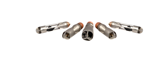
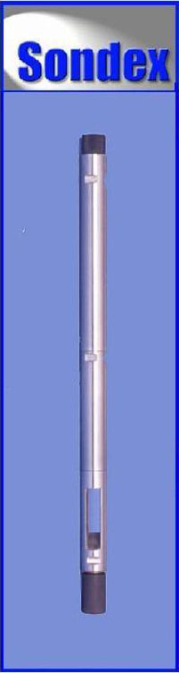
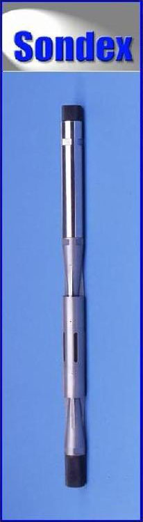
1 3/8” SHORT COMBINATION PL TOOLSTRING
 |
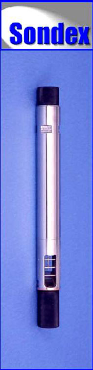
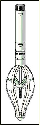
DESCRIPTION This is easily transported toolstring, designed for use where access is restricted. The basic string, with Flowmeter, Temperature, Capacitance, Density, Gamma, Pressure & CCL sensors, can be used for Memory or Surface Readout operations; it can also be extended to include other Sondex tools and will operate a variety of flowmeter mechanical sections. For transportation in a small case, the string breaks down into very short sections. These hae pressure isolation ans can have other tools such as Centralisers, Knuckle Joints ect. Fitted between them. KEY POINTS
SPECIFICATIONS
|
Nhóm Marketing
Fluid Density
 |
DESCRIPTION
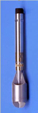
The Sondex FDR provides a reliable, durable and comparatively safe means of measuring fluid density at all well deviations. The tool uses a low energy Americium‑241 gamma ray source with radiation levels approaching background at a distance of only one metre from the tool. The tool has been re‑designed to be immune to the effects of radioactive scale. A radiation shield is provided which can be locked on the tool so that the source can be left in place between jobs. As the tool is unaffected by gravity or pressure fluctuations, it is able to operate reliably in all orientations from vertical to horizontal, and at all flow rates.
OPERATING PRINCIPLE Gamma rays are emitted by the RA source at one end of a measuring cell through which the well fluid passes. At the opposite end of the cell a scintillation detector provides a count rate which is a logarithmic function of the fluid density. The scintillation detector is temperature stabilized and matched to the gamma energy of the source. The tool may be calibrated in air and fresh water using Sondex supplied multipliers to derive calibration values applicable to oil and saltwater densities. SPECIFICATIONS
|
 |
BENEFITS:
|
 |
|
|
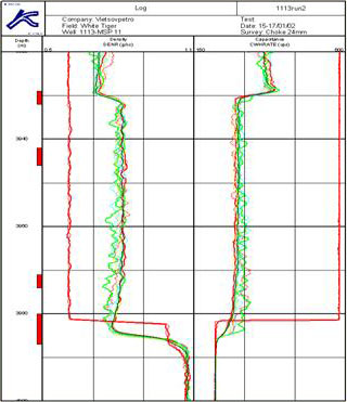
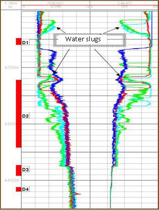
The combination of capacitance & density tool is helpful to identify the patterns of fluid flow in vertical / horizontal / highly deviated wells... |
Nhóm Marketing
Downhole Pressure Measurement
 |
DESCRIPTION
For high precision downhole pressure measurement, we use Sondex quartz pressure gauge tool, employing an industry standard quartz crystal pressure transducer. The tool provides both pressure and gauge temperature outputs.
OPERATING PRINCIPLE
Fluid pressure applied to the quartz tension member changes the resonant frequency of the quartz crystal. Thermal compensation of the sensor and measurement of its temperature allows the calculation of very accurate, high-resolution downhole pressures. Pressure readings are digitized to 24-bit resolution and gauge temperature to 16 bits and transmitted on one channel of the telemetry system simultaneously with other logging signals. In surface readout applications two pressure tools can be used with output from both tools transmitted in a single digital channel.
SPECIFICATIONS
|
|
Benefits:
|
 |
 |
The study of hydrodynamic characteristics is one of the most important methods to monitor production life of reservoir. It consists of:
|
Nhóm Marketing
Capacitance Water Holdup
 |
DESCRIPTION
The Sondex Capacitance Water Hold‑up Tool essentially measures the proportion of water in the well fluid. The design of the fluid flow path through the tool ensures representative sampling of the fluid in the well and ease of cleaning. The tool is most responsive up to 45% water cut, above which it starts to saturate as the conductive phase becomes dominant. In high water cut flows presentation scales can be expanded to indicate hydrocarbon entry that may not be detected by density tools. Also, though the tool is primarily a water holdup tool, because the tool has slightly different frequencies in gas and oil, in water free high Gas Oil Ratio wells it can be used to emulate a density tool as an indicator of GOR, but with higher resolution. OPERATING PRINCIPLE The tool is essentially an annular capacitor with the central probe and external cage acting as the capacitor plates and the well fluid flowing between the plates as the dielectric. Water has a high dielectric constant and hydrocarbons have low dielectric constants thus the output frequency of the tool changes in relation to the changing average dielectric constant, or water / hydrocarbon ratio, of the fluid flowing through the tool. Water holdup is determined by reference to a holdup / fractional response chart. SPECIFICATIONS
|
 |
BENEFITS:
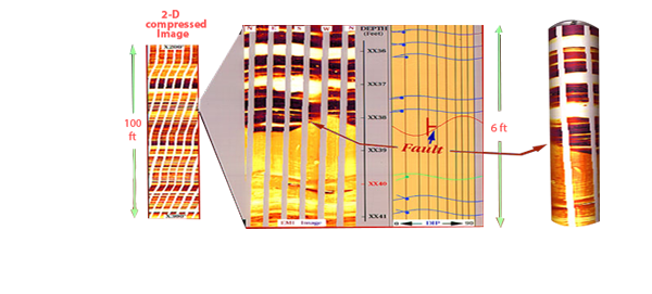
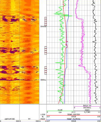
The plot opposite shows the productive zones against the fractured zones observed clearly by CAST-V in the White Tiger fractured basement reservoir
|
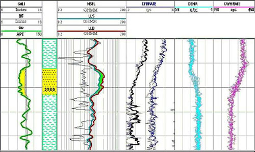 |
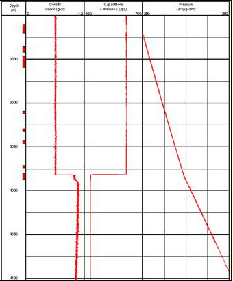
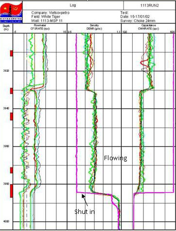
Entry of fluid is clearly indicated in the permeable zone as per CFBRATE, DENR and CWHRATE.
Nhóm Marketing
DownHole Temperature Measurement
 |
DESCRIPTION
The Platinum Resistance Thermometer is used to give a high precision reading of wellbore temperature. It outputs temperature data as a digital word allowing for very high resolution. Because of the small size of the tip it also has a very rapid response time, which minimizes the effects of differing line speeds. It can be run alone, or as part of a string of Production Logging tools.
OPERATING PRINCIPLE
The change of resistance of a length of platinum wire with changing well temperature is used to drive a Voltage Controller Oscillator. The frequency output from the VCO is digitized and encoded on the line. The high thermal conductivity copper tip is isolated with a low thermal conductivity body, which allows for high-resolution measurement even with high differential temperatures between the well fluid and the tool body.
SPECIFICATIONS
|
 |
Benefits:
|
|
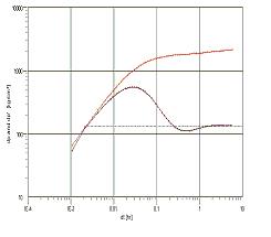
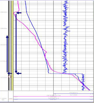
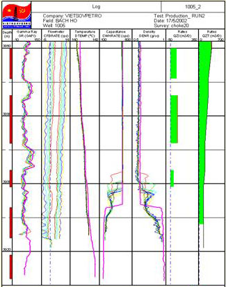
When downhole pressure is lower than bubble point pressure, associated gas is released. This gas could result in a temperature anomaly due to Joule – Thomson effect as shown in the plot opposite. |
|
 |
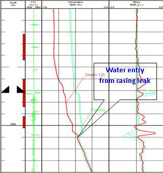
This plot indicates flow behind casing at 240m3/d flow rates. The temperature curve shows flow behind the casing from 3800m down to 4176-4180m, where it enter the casing. |
Nhóm Marketing
Flowmeters
 |
DESCRIPTION The Continuous Spinner Flowmeter are disgned for logging in tubing or sand screened well. The spinner rotates continuously and is supported by roller bearings each end. This performs in all well orientations from vertical to horizontal, in very high fluid velocity such as gas wells. The Caged Full Bore Flowmeter – CFB provides added protection to its impeller when used in wells with large ID gas lift mandrels and in horizontal wells. By allowing a large diameter impeller to pass through small diameter tubing, accurate flowrates covering a large cross section of the casing may be measured.
OPERATING PRINCIPLE CFS: The spinner is mounted between roller bearings and rotation detection is through zero drag Hall effect devices, giving very low threshold and optimizing low flow measurement at high flowrate. CFB: it may be closed down to tool diameter while running or pulling out of hole, and opens automatically to casing size when it leaves the tubing to enter the casing. Should a restriction be encountered during logging, the flowmeter will close and fold the spinner until the restriction is passed, thus avoiding damage to the blades.
SPECIFICATIONS |
||||||||||||||||||||||
 |
|
|
|
APPLICATIONS
CFS: Production Profile in Tubing across Sliding Side Doors. Offers better protection in wells with debris.Logging inside sand screens/slotted liners. Injection MonitoringCFB:
Horizontal and Highly Deviated Wells Full Bore Production Profile Full Bore Injection Profile Low Flow Rates The Flowmeters have been used by VIETSOVPETRO L&TD since 1991 with more than 200 jobs conducted in over 100 wells of White Tiger and Dragon Field |
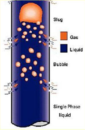
| Downhole multiphase flow likely encountered in production well.
Production logging in multi-phase flow wells has the same target as in the single-phase wells, as isolated interval detection anomalous rate changes clarification.
|
 |
Nhóm Marketing
Memory Production Logging System
|
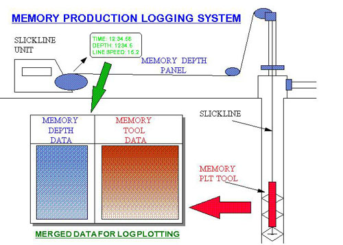
In memory production logging the production logging tools are run on non conducting wireline (slickline) or on coiled tubing. Power is supplied by a lithium battery at the top of the string. Instead of data being sent up the line the telemetry is decoded and data is stored in a memory tool according to a pre-programmed sample rate. Simultaneously depth and line speed data is recorded at surface in memory. After the tools are recovered from the well the two sets of data are merged with output files in ASCII format of depth, line speed and tool responses. These ASCII files are read into log plotting software and after depth correlating plotted as production logs.
|
 |
Nhóm Marketing
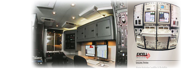
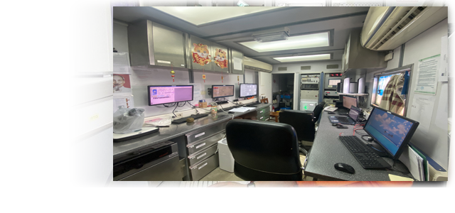
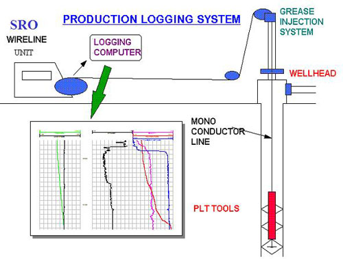
Surface Readout Production Logging System
|
INTRODUCTION In surface readout production logging the production logging tools are run on conducting wireline which is run from surface through a pressure control system (usually grease injection). Power is sent down the line and data from the production logging tools is relayed up via a telemetry system and decoded. This data is merged with depth and line speed data from the wireline unit’s measuring head and the logging data is displayed real time. |
|
|
Nhóm Marketing