L&TD
LOGGING & TESTING DIVISION
Sản phẩm dịch vụ
DownHole Temperature Measurement
 |
DESCRIPTION
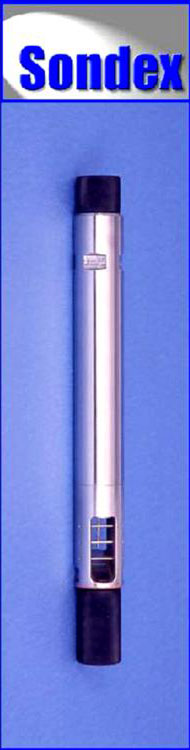
The Platinum Resistance Thermometer is used to give a high precision reading of wellbore temperature. It outputs temperature data as a digital word allowing for very high resolution. Because of the small size of the tip it also has a very rapid response time, which minimizes the effects of differing line speeds. It can be run alone, or as part of a string of Production Logging tools.
OPERATING PRINCIPLE
The change of resistance of a length of platinum wire with changing well temperature is used to drive a Voltage Controller Oscillator. The frequency output from the VCO is digitized and encoded on the line. The high thermal conductivity copper tip is isolated with a low thermal conductivity body, which allows for high-resolution measurement even with high differential temperatures between the well fluid and the tool body.
SPECIFICATIONS
|
 |
Benefits:
|
|
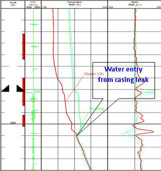
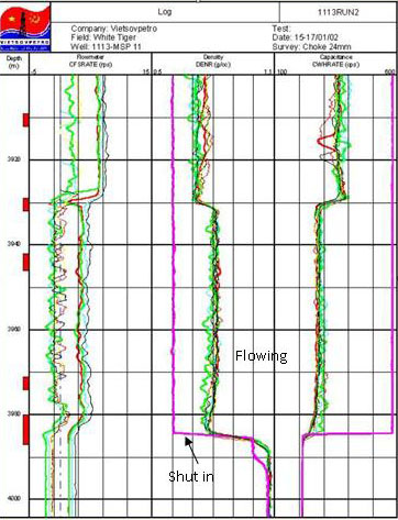
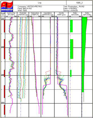
When downhole pressure is lower than bubble point pressure, associated gas is released. This gas could result in a temperature anomaly due to Joule – Thomson effect as shown in the plot opposite. |
|
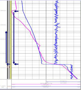 |
This plot indicates flow behind casing at 240m3/d flow rates. The temperature curve shows flow behind the casing from 3800m down to 4176-4180m, where it enter the casing. |
Nhóm Marketing
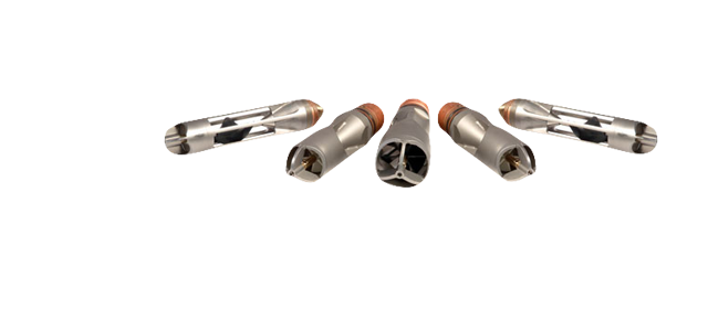
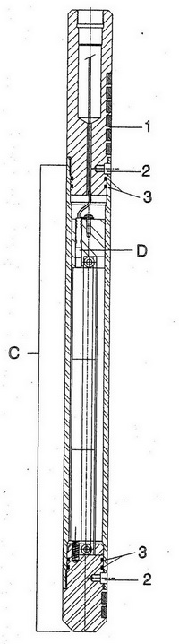
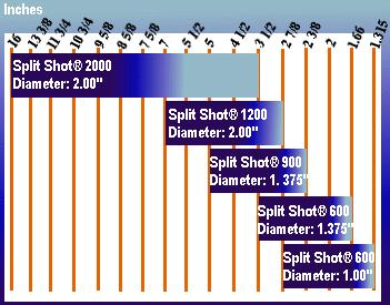
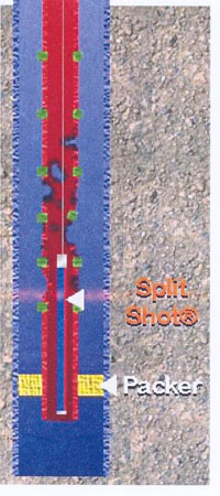
Split Shot Cutter 1.375 ”to 2” O.D Segmented Cutter
|
Specifications
Casing and Tubing Sizes
Benefits and Features Using |
 |
|||||||||||||||||||||||||||||||||||
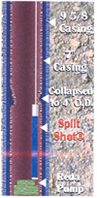
No other cutter would go down |
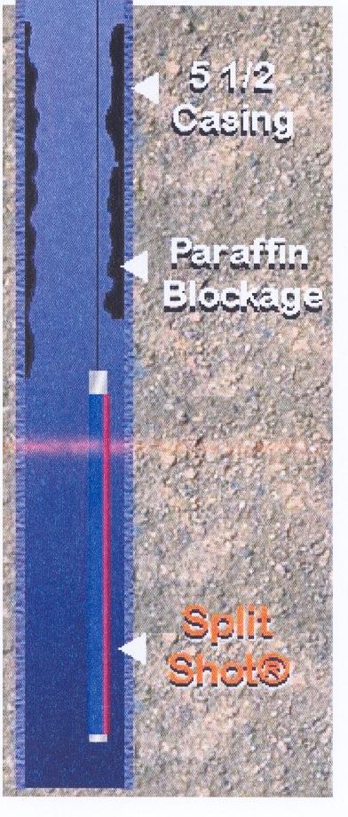
Paraffin blockage |
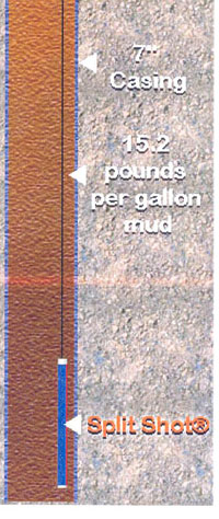
Mud |
Corroded tubing |

3-1/2” Tubing cut with the Split Shot Cutter |
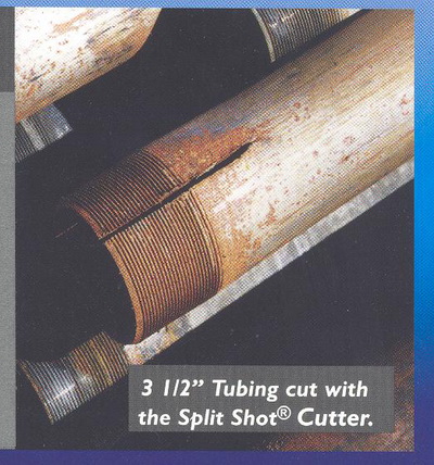
3-1/2” Tubing cut with the Split Shot Cutter |
Nhóm Marketing
Basroc A Special Software For Basement
|
The fractured basement reservoir is characterized by a very complex structure and it requires a special method to evaluate. BASROC is one of those. The software BASROC was developed by VSP in 1992, for application in reservoir evaluation and simulation for Bach Ho oil field. In order to increase the utility and accuracy in the determination of reservoir parameters, this software has been upgraded continuously. Version 3.0 is the latest version now used in evaluation and simulation of basement reservoirs in Bach Ho, Rong and other oil fields. |
Reservoir model – two porosities and two permeabilities:
|
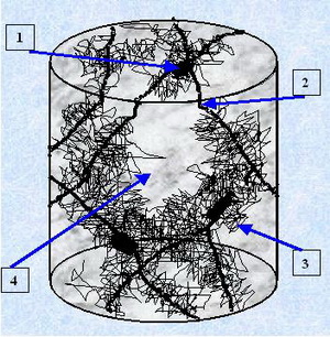 |
Pig.1: Pore Space Structure Fractured granite.
1-Vug Porosity, 2 -Macro Fracture, 3- Micro Fracture, 4-Unchanged Rock. |
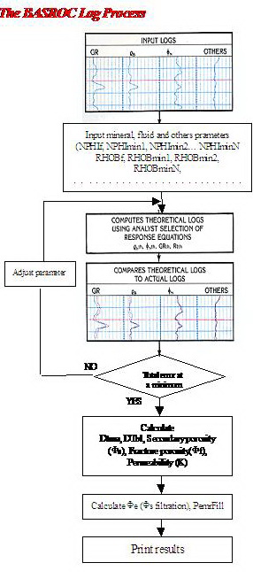 |
The important features in BASROC 3.0
BASROC is an advanced multi-mineral log analysis program. It computes the most probable formation mineralogy and total porosity, open porosity using a multi-log, least-squares inversion technique. It is particularly valuable in areas of mixed lithologies, special minerals and two porosities systems. Grade porosity by filtered method. Calculate fracture porosity by looped technique. Export the result in the tabular and bitmap files. Any Microsoft Windows supported printing device.
|
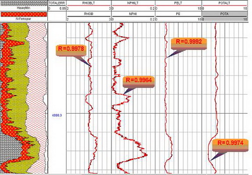
Fig. 2 – The comparison of theoretically synthetic and practical curves
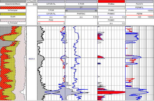
Fig. 3 – Results of BASROC processing for fractured Basement |
Nhóm Marketing
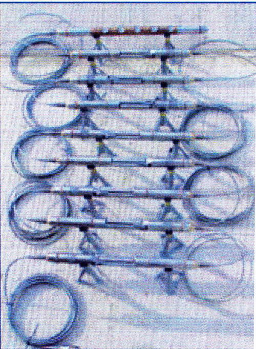
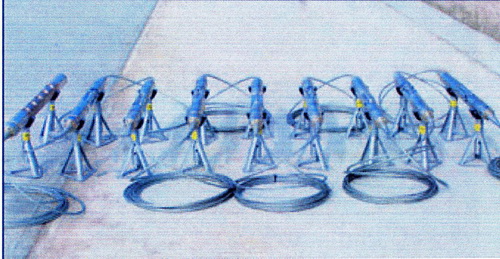
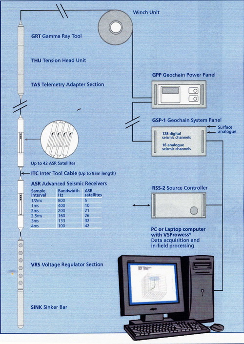
Downhole Tool GeochainTM 42 Level Digital VSP Array
|
Main Features: • Up to 42 satellites • Standard 7 conductor wireline. • Real time data transmission • 3 component gimballed • 24bit Delta-Sigma convertors • 180oC temperature rating • Unique Active Cooling System for continuous operation at 180oC • 20000psi pressure rating • Up to 95m between satellites |
8 satellites and VRS |
|
GeochainTM – an 8 level array with VRS
|
Nhóm Marketing
WaveSonic Log
|
WAVE SONIC - Halliburton's Third Generation Ultra-Reliable, Crossed Dipole Sonic Tool THE BETTER KEY TO FRACTURE RESERVOIR EVALUATION |
 |
Tool specification
Halliburton's WaveSonic crossed dipole sonic tool makes it easy to determine fast and slow shear wave travel times and their orientation in the formation. With the WaveSonic, you can even calculate minimum and maximum principal stresses and stress field orientation by combining oriented slowness data with overburden and pore pressure data. This information is vital for mechanical analysis, wellbore stability and production enhancement treatment design. Sonic anisotropy and the orientation of the anisotropy can be used to determine the orientation of natural fractures. Sonic attributes such as P wave slowness, fast and slow shear wave travel time, identification of compressive fluids in the pore space, and anisotropy orientation allow for better 3 D seismic analysis. |
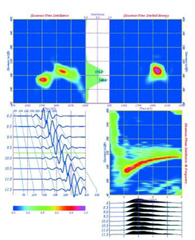 |
This is an example of a semblance diagnostic plot of the waveform data from the eight waveforms. In the circle is a section of a WaveSonic log showing Monopole P wave slowness and semblance quality monopole refracted Shear wave |
| The Product of Halliburton’s WaveSonic tool service provides simultaneous monopole and crossed dipole sonic information. P‑wave and S‑wave slowness can be obtained in formation conditions ranging from poorly consolidated high porosity gas saturated sandstones to low porosity carbonates. The flexural wave energy is propagated from a low frequency on‑depth crossed dipole bender‑bar source. The low frequency flexural wave travels at the true shear slowness of the formation. As a result, dispersion corrections for shear have slowness are not required. A low frequency monopole source is utilized, so the P‑wave and flexural wave data have similar depths of investigations well beyond any near wellbore alteration. Other benefits include:
- No need for dispersion corrections for slowness determination. ‑ No depth shifting of waveform data for anisotropy analysis.
|
Nhóm Marketing
Flowmeters
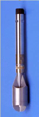 |
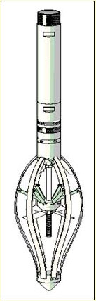
DESCRIPTION The Continuous Spinner Flowmeter are disgned for logging in tubing or sand screened well. The spinner rotates continuously and is supported by roller bearings each end. This performs in all well orientations from vertical to horizontal, in very high fluid velocity such as gas wells. The Caged Full Bore Flowmeter – CFB provides added protection to its impeller when used in wells with large ID gas lift mandrels and in horizontal wells. By allowing a large diameter impeller to pass through small diameter tubing, accurate flowrates covering a large cross section of the casing may be measured.
OPERATING PRINCIPLE CFS: The spinner is mounted between roller bearings and rotation detection is through zero drag Hall effect devices, giving very low threshold and optimizing low flow measurement at high flowrate. CFB: it may be closed down to tool diameter while running or pulling out of hole, and opens automatically to casing size when it leaves the tubing to enter the casing. Should a restriction be encountered during logging, the flowmeter will close and fold the spinner until the restriction is passed, thus avoiding damage to the blades.
SPECIFICATIONS |
||||||||||||||||||||||
 |
|
|
|
APPLICATIONS
CFS: Production Profile in Tubing across Sliding Side Doors. Offers better protection in wells with debris.Logging inside sand screens/slotted liners. Injection MonitoringCFB:
Horizontal and Highly Deviated Wells Full Bore Production Profile Full Bore Injection Profile Low Flow Rates The Flowmeters have been used by VIETSOVPETRO L&TD since 1991 with more than 200 jobs conducted in over 100 wells of White Tiger and Dragon Field |
| Downhole multiphase flow likely encountered in production well.
Production logging in multi-phase flow wells has the same target as in the single-phase wells, as isolated interval detection anomalous rate changes clarification.
|
 |
Nhóm Marketing
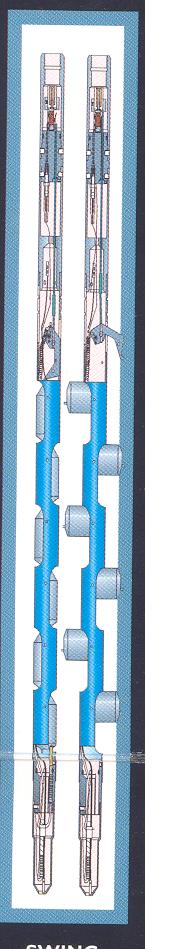
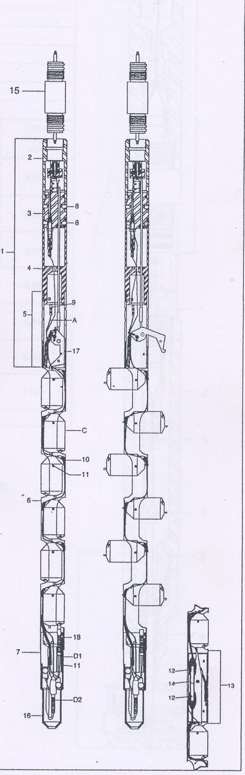
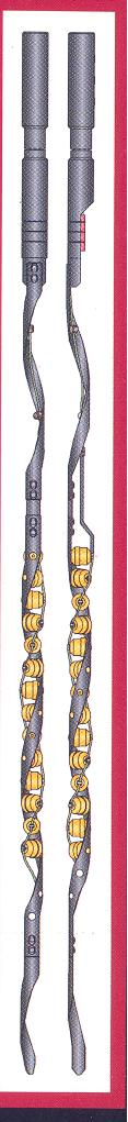
Thru Tubing Perforation System (Swing Jet-180 Phased System)
|
Specifications
Benefits and Features - Swing jet can perforate at under balanced and makes the shell crater deeper (about 10 ”) in formations. - Swing jet makes increasing recovery factor and can pass through Christmas tree, tubing … and perforate under packer. - Swing jet can perforate during production. - Swing jet carries larger charges than reguler through tubing guns. |
 |
 |
||||||||||||||||||||||||||||||||||||||||||||||||||||||||||||||||||
|
Specifications
|
||||||||||||||||||||
Benefits and Features Makes increasing recovery factor of hydrocarbon saturated zone in oil fields. - Can pass through Christmas tree, tubing. - Can perforate under balance and under packer. - Can perforate during producing process. - The length of the gun may be up to 10 meters. |
 |
 |
Nhóm Marketing
Imager Analysis
|
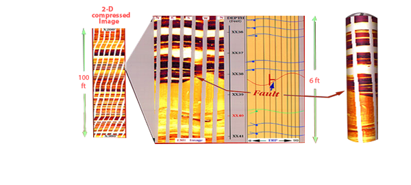
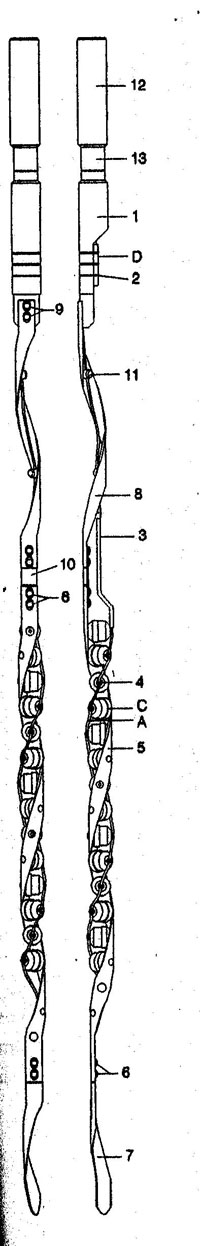
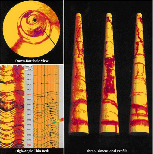
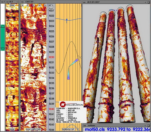
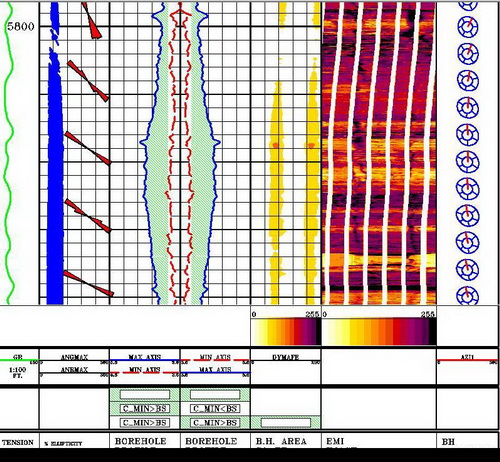
Imager is an interactive image interpretation software package used to present and analyze vector data from the Circumferential Acoustic Scanning Tool (CAST), Electric Micro Imaging (EMI) tool, the Formation MicroScanner™ (FMS) tool, and the Fullbore Formation MicroImager (FMI) tool. Imager allows displaying the logged data graphically in various ways. The images may be enhanced to emphasize certain features, facilitating the interactive calculation of dip and fracture information.
For CAST service, Using Imager, we can:
For EMI Service, using Imager, we can:
Calculate the dip angle and direction of bedding, fractures |
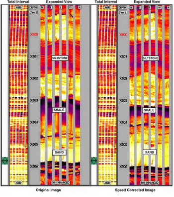 |
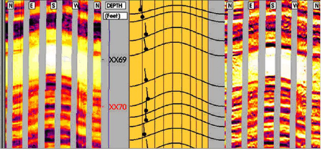
Comparison of EMI Images with speed correction applied. |
|
Imager analysis program window Geometry and Stress analysis |
Nhóm Marketing
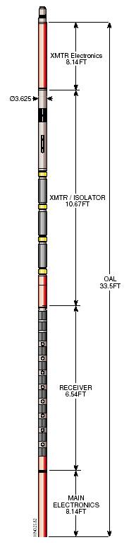
Downhole Tool ASR-1 Advanced Seismic Receiver
 The ARS-1 Specifications
General
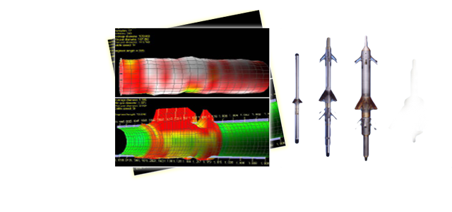
The ASR geophones a compact three component electromechanical downhole geophone. It is disigned for use in wells up to 20000psi and 200oC and provides fast arm cycle time with an arm force to weight ratio of 5:1.
Locking Arms The standard arm will accommodate boreholes from 5” to 13”, the short arm will accommodate borehole from 3 ½” to 9” and an extended arm can be use to increase this range to 22”. The locking force is constant to within 20% throughout its operating range and will lock into 9 5/8” casing in fifteen seconds when fitted with the standard arm. Gimbal Element The tool is provided with a three component gimballed package as standard using one high sensitivity SM4 high temperature element per axis. The gimbal assembly with faithfully follow any borehole deviation from vertical through to horizontal and slightly beyond. Nhóm Marketing |
FullWave Sonic Log
 |
The sonic logging system developed by Halliburton provides more acoustic information than ever before. From 1997, Vietsopetro L&TD successfully evaluated potential zones in fractured basement using FWST data.
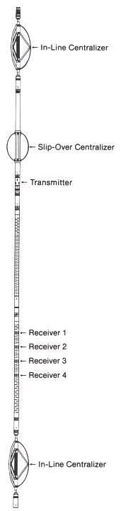
Using a piezoelectric transmitter and four long‑spaced receivers, the FWS system records the entire acoustic wavetrain. Digital processing techniques extract compressional, shear, and Stoneley t; shear wave and compressional wave amplitudes; and Stoneley wave attenuation. These basic measurements provide valuable information on rock types, gas zones, porosity naturally fractured intervals, formation elastic properties, stress field around the borehole, permeability, and acoustic impedance.
FWS APPLICATIONS
|
|
FWST – An effective tool to evaluate the potential zones in fractured basement.
FWST has been used by Vietsopetro L&TD to investigate the characteristics of fractures in basement of Cuu Long basin. The tc, ts and tst and energy attenuation measurements have been used for: - Detection of naturally fractured zones. - Indication of permeability variations with depth from Stoneley wave attenuation. - Lithology identification by means of velocity ratio, ts /tc In fact, surveys in basement of Cuu Long basin indicated that FWST is an effective tool for evaluation of fracture zones in basement. |
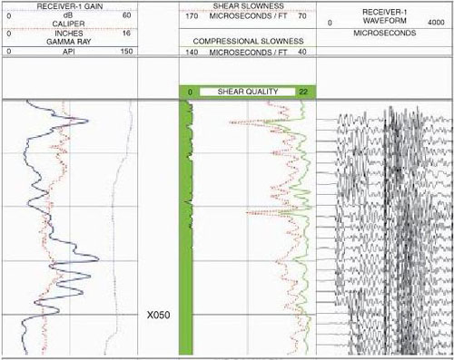 |
This FWS primary log example displays the raw waveform data from Receiver 1 in the right track. Processed results, including compressional and shear slowness curves (tc and ts), are shown in the center track, along with a shear slowness quality indicator Caliper and Gamma Ray information, along with a gain curve, are displayed in the left track |
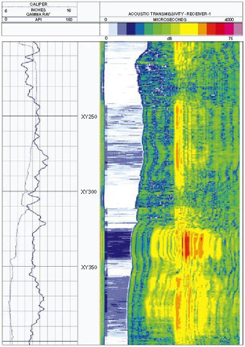 |
Instantaneous Waveform Characteristics IWC analysis allow users better evaluation of fracture zones as spectrum of amplitude, phase and frequency of waveform |
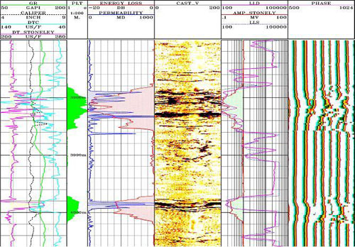 |
This plot shows potential zones in White Tiger fractured basement by mean of the energy loss of Stoneley wave (Track 5). In fact, these zones are highly productive. |
Nhóm Marketing
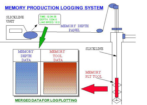
Memory Production Logging System
|
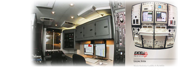
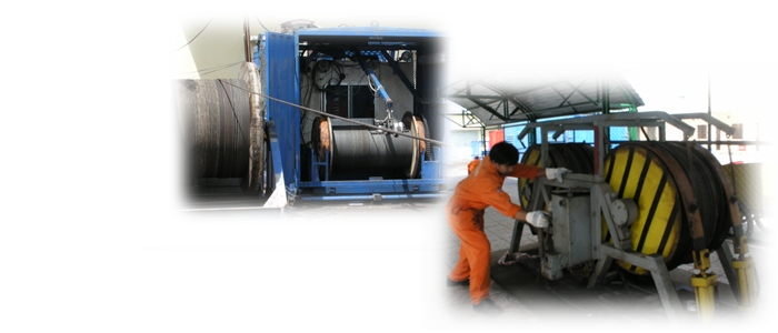
In memory production logging the production logging tools are run on non conducting wireline (slickline) or on coiled tubing. Power is supplied by a lithium battery at the top of the string. Instead of data being sent up the line the telemetry is decoded and data is stored in a memory tool according to a pre-programmed sample rate. Simultaneously depth and line speed data is recorded at surface in memory. After the tools are recovered from the well the two sets of data are merged with output files in ASCII format of depth, line speed and tool responses. These ASCII files are read into log plotting software and after depth correlating plotted as production logs.
|
 |
Nhóm Marketing