L&TD
LOGGING & TESTING DIVISION
Sản phẩm dịch vụ
Cased - Hole Logging

1. INTRODUCTION
- Formed in 1991
- Consist of
- 02 Production wire-line teams
- 02 Casing inspection teams
- 01 Memory team. ( in 2003)
- Personal : 21
- Engineer: 12
- Skilled worker: 9
- Perfomed
- Over 300 PLT jobs
- Over 200 Casing/tubing inspection jobs
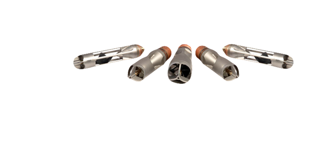
Electrical Micro-Imager
|
EMI – COST-EFFECTIVE TECHNOLOGY FOR FORMATION AND RESEVOIR EVALUATION |
 |
Tool specification
|
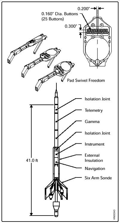
| In today’s economically-sensitive energy world, thorough and cost-effective reservoir evaluation is more important than ever before. Halliburton’s Electrical Micro Imaging (EMI™) service is a new process designed to meet these needs by producing core-like electrical micro-conductivity images of the formation sequence encountered in the wellbore.
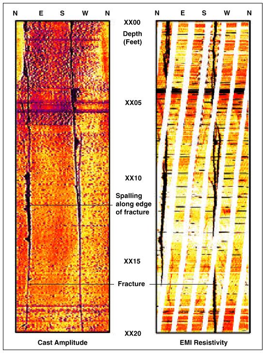
Based on the Award-Winning Six-Arm Dipmeter (SED ™) Technology. The mechanically proven architecture of the EMI is based on six articulating pads, each mounted on an independent arm, allowing improved electrode-to-formation contact. Quality formation images are achieved using 150 pad-mounted sensors distributed 25 on each of the six pads. This results in a measurement resolution of 0.2 inches. Conventional dipmeter information is recorded in addition to the image data. Operating Principles The EMI tool provides an image of the borehole wall by measuring and mapping formation micro-conductivity with the pad-mounted button electrodes. Current is emitted from the lower section of the tool into the formation. Part of this current (survey current) flows from the pad-mounted buttons, but the rest (focusing current) is used for focusing and maintaining high-resolution measurement. The current of each button is recorded as a curve, sampled at 0.1 inch (0.25 centimeters), or 120 samples per foot. The curves reflect the relative micro-conductivity variations within the formation. These current variations are converted to synthetic color or gray-scaled images. Light colors represent low micro-conductivity, while dark colors reflect high micro-conductivity zones. Centralization above and below the EMI mandrel optimizes the distribution of the six pads across the circumference of the borehole, especially in horizontal and highly deviated wells. A full navigation package, consisting of three orthogonal fluxgate accelerometers and three orthogonal magnetometers, is included in the EMI tool to provide accurate information on tool position, motion, direction, and orientation within the borehole. The enormous amount of data acquired while logging is transmitted digitally to the surface unit via Halliburton’s proven Digital Interactive Telemetry System (DITS). |
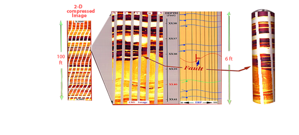
| IMAGING – THE KEY TO BETTER ANALISYS
Real-time images are produced at the wellsite. Detailed post-acquisition analysis of the image data is made with high-performance InterView ™ analysis software. Image analysis and enhancement techniques are available for precise identification of formation reservoir characteristics, including the following. |
|
 |
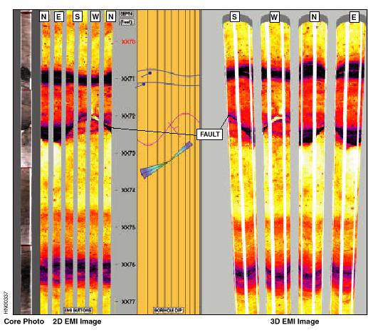
Comparison of EMI image and fullbore core, showing abrupt fault with no associated drag. |
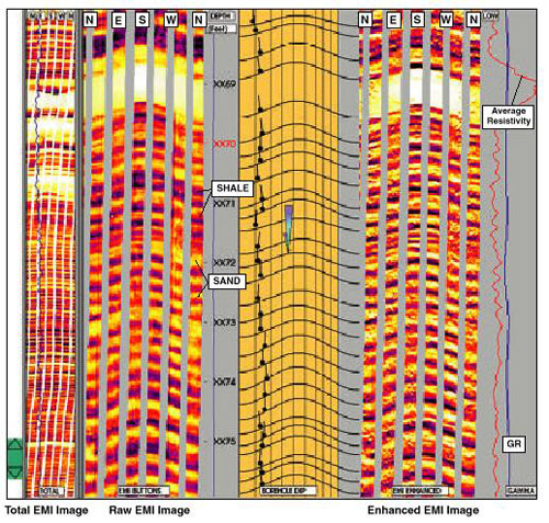 |
Thin bed response of the EMI tool in a laminated sand/shale sequence. |
Nhóm Marketing
Capacitance Water Holdup
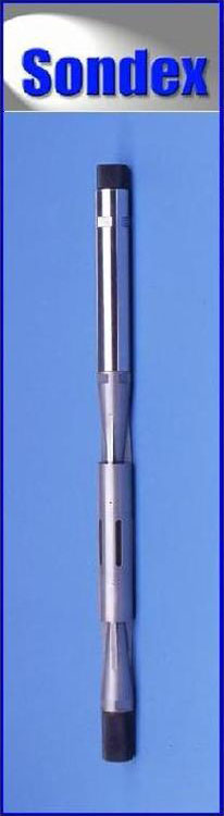 |
DESCRIPTION
The Sondex Capacitance Water Hold‑up Tool essentially measures the proportion of water in the well fluid. The design of the fluid flow path through the tool ensures representative sampling of the fluid in the well and ease of cleaning. The tool is most responsive up to 45% water cut, above which it starts to saturate as the conductive phase becomes dominant. In high water cut flows presentation scales can be expanded to indicate hydrocarbon entry that may not be detected by density tools. Also, though the tool is primarily a water holdup tool, because the tool has slightly different frequencies in gas and oil, in water free high Gas Oil Ratio wells it can be used to emulate a density tool as an indicator of GOR, but with higher resolution. OPERATING PRINCIPLE The tool is essentially an annular capacitor with the central probe and external cage acting as the capacitor plates and the well fluid flowing between the plates as the dielectric. Water has a high dielectric constant and hydrocarbons have low dielectric constants thus the output frequency of the tool changes in relation to the changing average dielectric constant, or water / hydrocarbon ratio, of the fluid flowing through the tool. Water holdup is determined by reference to a holdup / fractional response chart. SPECIFICATIONS
|
 |
BENEFITS:
The plot opposite shows the productive zones against the fractured zones observed clearly by CAST-V in the White Tiger fractured basement reservoir
|
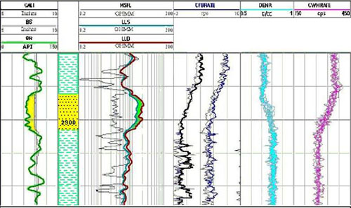 |
Entry of fluid is clearly indicated in the permeable zone as per CFBRATE, DENR and CWHRATE.
Nhóm Marketing
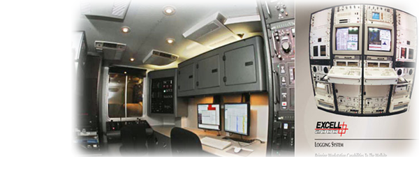
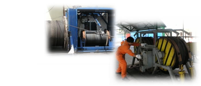
Mud Logging Services
| I. INTRODUCTION
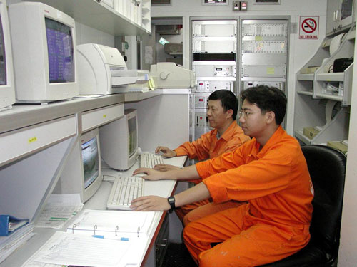
Same as other parts of L&TD, Mudlogging services have also been utilized in all Vietsovpetro wells. During drilling operations Mudlogging services perform the following functions: drilling operation monitor and control, geological data and information collection, drilling operation safety awareness. For this work the MudLogging team has 24 highly trained and competant Engineers good experience in Mudlogging work. Most of them have more than 10 years working experience. In order to keep pace with new technological development, a number of relevant training courses are given to all staff to ensure that good quality service is achieved in all jobs. At present, we are using the Geoservices ALS-2 Mud Logging Units (Advanced Logging System, second generation). In addition, we co-operate with domestic companies to design, manufacture and put Advanced Security System; into operation and upgrade & improve the completeness of equipment. Mud Logging Unit equipment is regularly replaced and upgraded in compliance with modern technology to secure operational correctness and stability. |
 |
Nhóm Marketing
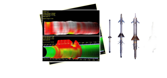
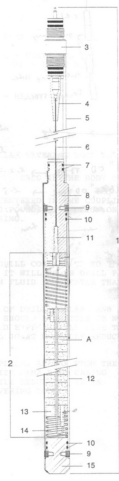
Drill Collar Severing Tool (Mach Wave Generator Type 1-3/8” and 2”)
· Benefits and Features
Recommended usage of largest size drill collar severing tool for the bore or restriction size encountered.
Drill Collar: Severing tool should be centered in the body of the collar.
Drill Pipe: Severing tool should be centralized in the coupling with approximately 10,000 pounds of tension on the string at time of firing. - Severing tool has been used many times to release drill collar or heavy drill pipe from the well.
|
 |
Nhóm Marketing
Emeraude
|
Emeraude has been uesd in Vietsovpetro L&TD since 2000.
This is one of the best production log interpretation softwares, an impossibly missing tool of reservoir monitoring.
In recent years production logging has moved from being considered as the tool of last resort to a powerful quantitative method that takes its own place in the set of data acquisition tools for the reservoir engineer.
This has been due to two factors: the lowering of acquisition costs using 'fit‑for‑purpose' tools and shifting the interpretation into the hands of the end‑user engineer by the development of client as opposed to tool focused software; Emeraude. In the past, PL was a highly specialized business. Data acquisition was made using expensive tools and interpretations were performed by engineers poring focused on the mechanical aspects of the tools and looking for specific well problems but not on the reservoir under study.
The realization of the value of the results of a production logging surveillance survey has given the reservoir engineer a powerful new tool in the drive for the more accurate and refined reservoir characterization.
All the major and most of the independent service companies as well as many operating companies now use Emeraude. Emeraude is seen as the industry standard allowing a common platform for communication and interpretation between service companies and the operators.
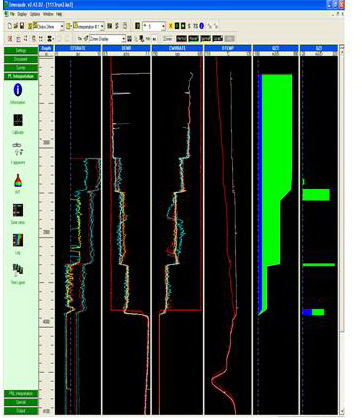
The latest version of Emeraude, Version 2.42, includes facilities for the interpretation of highly deviated to horizontal wells with specific processing for multiple‑probe tools. These include the generation of holdup/bubble images and the display of holdups inside a representation of the wellbore.
KAPPA remains committed to the ongoing development of the industry standard PL interpretation package, Emeraude. |

| METHODOLOGY
Reference channels / Spinner calibration An interpretation starts with the selection/definition of a Reference Channel for each available measurement. From the spinner passes ‑ if a spinner has been run ‑ the in‑situ calibration can be calculated on user selected calibration zones and a resulting apparent velocity channel is generated. PVT The fluid type is defined, and the PVT properties of each phase are represented using a wide variety of Black‑Oil correlations, for bubble point or dew point fluids. Each correlation can be matched to a set of user entered constraint points, to ensure that the model values are representative. |
 |
|
Zone Rates When all the required information has been entered, the user defines a number of calculation zones, outside the assumed inflow zones. Based on the fluid types and the available measurements Emeraude suggest a list of possible flow models and, for the one retained by the user, the software automatically calculates the cumulative phase rates on all the calculation zones. The rates are obtained using non‑linear regression, which makes it possible to supply any relevant set of inputs, and to possibly use redundant information. The solution rates are found by minimizing the error between measured and simulated values. Each difference (or residual) can be weighted separately. The following measurements are viable regression inputs: density, spinner apparent velocity, holdup of any phase, velocity of any phase, rate of any phase, mixture rate, mixture velocity, and temperature. The measurements may be continuous or stationary. The simulation is based on a full range of flow models from single‑phase to full 3‑phase situations, and a number of slippage correlations for those cases, in vertical or deviated wells. Specific models are also provided to handle flow re‑circulation (apparent down flow) as well as flow through a standing water/liquid column. In the Zone Rates option, the backbone of the interpretation, all the results relevant to the calculation on any particular zone can be visualized such as the flow regime, the slippage velocities, holdups, the flow map for the selected correlation, etc. The model / correlations can be modified, the velocities can be changed manually, and the surface conditions can be matched. etc. The solution can be examined in terms of actual contributions (rather than cumulative). Global Regression, solving simultaneously for all the contributions on the entire well, can be run if necessary. The Global regression can be used as a second path to impose constraints on the solution. Constraints can be individual sign constraints (producing zone or a thief zone). Contributions can be manually edited and/or fixed to a given value. This helps finding a coherent solution when standard methods fail. |
Nhóm Marketing
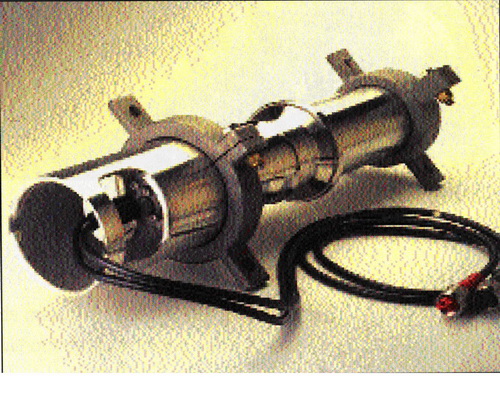
Airgun And RSS-2 VSP Source Controller
|
I/O Sleeve Guns
• Size: three sizes, with volumes of 10 in3,20 in3 or 40 in3. • Polarized timing coil • Measured standard deviation of 110µs with a 351µs dispersion • Tow clamps equipped with a top hat that minimizes electrical cable and air hose proplems during handing and RSS-2 VSP Source controller
• Automatic source array synchronisation • Window based software • Each RSS-2 controls up to 16 sources |
|
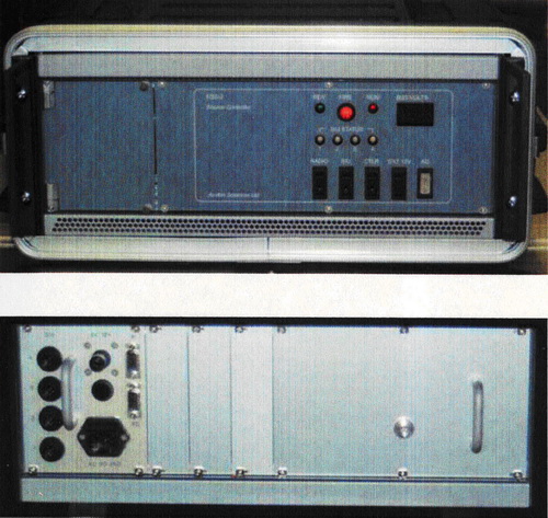 |
• Timing accuracy 0.1ms • Source signature telemetry • Readout of reservoir and gun pressure • Accepts hydrophone, shuttle, T/B coil etc • Automatic source switching from software
|
Nhóm Marketing
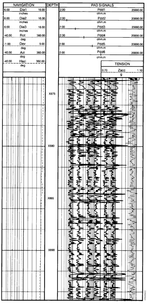
Dipmeter
Tool specification
|
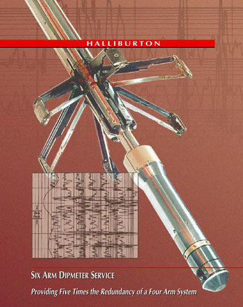 |
Six arm dipmeters employ six pad-mounted, focused current electrodes equally spaced about the main tool body. These electrodes measure resistivity at six azimuths about the borehole. These tools also measure borehole drift angle, drift azimuth, and borehole eccentricity. From this information software calculates the dip and strike of formations penetrated by the wellbore. The results are available in standard arrow, polar, and statistical plots and in tabular listings. These aid in identifying structural features such as regional dip, faults, reefs and unconformities. They also provide important information in determining depositional features such as cross bedding, foreset bedding and channel sand. Drift surveys, borehole profiles and fracture profiles are also produced from six-arm dipmeter measurements. With their six independently sprung caliper arms and their swiveled pads, Six-Arm Dipmeter achieve uniform contact |
| with the borehole wall. Thus, they are better able to accommodate borehole irregularities in both the circumferential and axial senses. Tool centralization is not a critical factor, even in deviated wells, and the effects of irregular tool motion are minimal.
Six-Arm Dipmeters can be run in any type of borehole liquid survey, even in oil-base muds. Application |
|
 |
Nhóm Marketing
DownHole Temperature Measurement
 |
DESCRIPTION
The Platinum Resistance Thermometer is used to give a high precision reading of wellbore temperature. It outputs temperature data as a digital word allowing for very high resolution. Because of the small size of the tip it also has a very rapid response time, which minimizes the effects of differing line speeds. It can be run alone, or as part of a string of Production Logging tools.
OPERATING PRINCIPLE
The change of resistance of a length of platinum wire with changing well temperature is used to drive a Voltage Controller Oscillator. The frequency output from the VCO is digitized and encoded on the line. The high thermal conductivity copper tip is isolated with a low thermal conductivity body, which allows for high-resolution measurement even with high differential temperatures between the well fluid and the tool body.
SPECIFICATIONS
|
 |
Benefits:
|
|
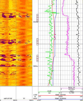
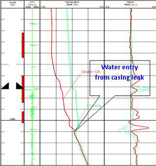
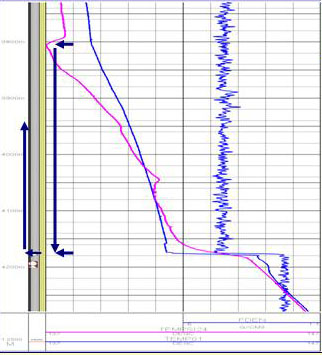
When downhole pressure is lower than bubble point pressure, associated gas is released. This gas could result in a temperature anomaly due to Joule – Thomson effect as shown in the plot opposite. |
|
 |
This plot indicates flow behind casing at 240m3/d flow rates. The temperature curve shows flow behind the casing from 3800m down to 4176-4180m, where it enter the casing. |
Nhóm Marketing
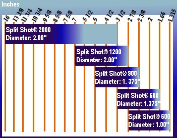
Split Shot Cutter 1.375 ”to 2” O.D Segmented Cutter
|
Specifications
Casing and Tubing Sizes
Benefits and Features Using |
 |
|||||||||||||||||||||||||||||||||||
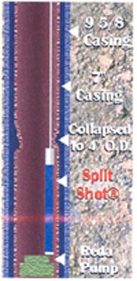
No other cutter would go down |
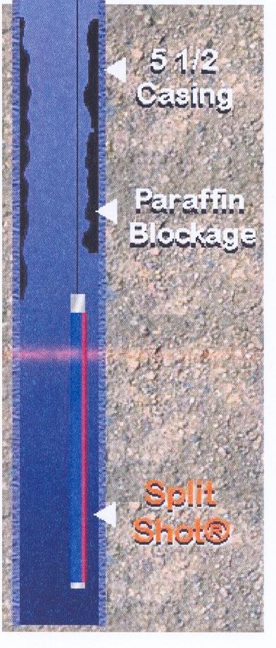
Paraffin blockage |
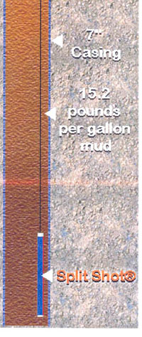
Mud |
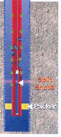
Corroded tubing |

3-1/2” Tubing cut with the Split Shot Cutter |
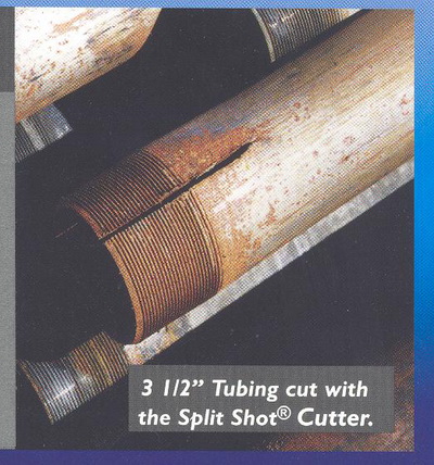
3-1/2” Tubing cut with the Split Shot Cutter |
Nhóm Marketing
Basroc A Special Software For Basement
|
The fractured basement reservoir is characterized by a very complex structure and it requires a special method to evaluate. BASROC is one of those. The software BASROC was developed by VSP in 1992, for application in reservoir evaluation and simulation for Bach Ho oil field. In order to increase the utility and accuracy in the determination of reservoir parameters, this software has been upgraded continuously. Version 3.0 is the latest version now used in evaluation and simulation of basement reservoirs in Bach Ho, Rong and other oil fields. |
Reservoir model – two porosities and two permeabilities:
|
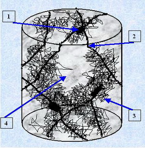 |
Pig.1: Pore Space Structure Fractured granite.
1-Vug Porosity, 2 -Macro Fracture, 3- Micro Fracture, 4-Unchanged Rock. |
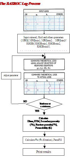 |
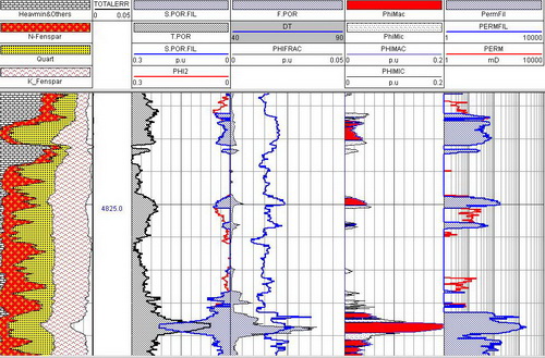
The important features in BASROC 3.0
BASROC is an advanced multi-mineral log analysis program. It computes the most probable formation mineralogy and total porosity, open porosity using a multi-log, least-squares inversion technique. It is particularly valuable in areas of mixed lithologies, special minerals and two porosities systems. Grade porosity by filtered method. Calculate fracture porosity by looped technique. Export the result in the tabular and bitmap files. Any Microsoft Windows supported printing device.
|
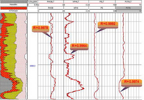
Fig. 2 – The comparison of theoretically synthetic and practical curves
Fig. 3 – Results of BASROC processing for fractured Basement |
Nhóm Marketing